Eurocode EN1992-1-1 - Column Design Examples
Overview
The Eurocode Design module provides comprehensive structural verification for concrete columns according to Eurocode 2 standards. It supports both rectangular and circular cross-sections with complete checks for bending, shear, torsion, and detailing requirements. The goal is simple: show exactly how the calculations are done, step by step, without any black boxes.
If something looks off, shout it out — engineers debating technical details is basically a sport, and if so, we’re happy to listen and learn.
Example of rectangular column design
This page shows how Strulab verifies a reinforced concrete rectangular column according to EN 1992‑1‑1:2004 + A1:2013.
1. Inputs
Section Definition Screen
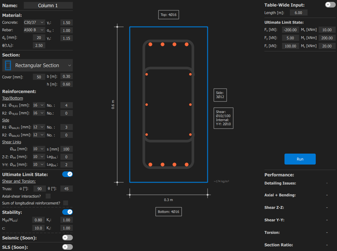
1.1 Name and material
- Name – Column name. (Column 1)
- Concrete – Concrete class. (C30/37)
- Rebar – Reinforcement class. (A500 B)
- dg – Largest nominal maximum aggregate size. (20mm)
- ϕ(t,t0) – Creep coefficient, defining creep between times t and t0, related to elastic deformation at 28 days.(2.50)
- γC – Partial factor for concrete. [EN1992-1-1 2.4.2.4] (1.50)
- αcc – Coefficient taking account of long term effects on the compressive strength and of unfavourable effects resulting from the way the load is applied. [EN1992-1-1 3.1.6] (1.00)
- γS – Partial factor for reinforcing. [EN1992-1-1 2.4.2.4] (1.15)
1.2 Section geometry
- Cover – Cover is the distance from the outer face of the nearest reinforcement (including links or stirrups) to the nearest concrete surface. [EN1992-1-1 4.4.1.1] (50mm)
- b – Section width. (0.30m)
- h – Section height. (0.60m)
1.3 Longitudinal Reinforcement
- ØTB,R1 – Diameter of top/bottom reinforcement R1. (16mm)
- No. – Number of bars for top/bottom R1. (4)
- ØTB,R2 – Diameter of top/bottom reinforcement R2.
- No. – Number of bars for top/bottom R2.
- ØSide,R1 – Diameter of side reinforcement R1. (12mm)
- No. – Number of bars for side R1. (3)
- ØSide,R2 – Diameter of side reinforcement R2.
- No. – Number of bars for side R2.
1.4 Shear Links
- ØExt – Diameter of external shear links. (10mm)
- s – Spacing of shear links. (100mm)
- ØInt – Diameter of internal shear links in the z-direction.
- LegInt. – Number of internal shear link legs.
- ØInt – Diameter of internal shear links in the y-direction. (10mm)
- LegInt. – Number of internal shear link legs. (2)
1.5 Ultimate Limit State
- α – Angle between shear reinforcement and the beam axis perpendicular to the shear force. [EN1992-1-1 6.2.3] (90o)
- θ – Angle between the concrete compression strut and the beam axis perpendicular to the shear force. [EN1992-1-1 6.2.3] (45o)
- Axial-shear interaction? – Consider interaction between axial force and shear.
- Sum of longitudinal reinforcement? – Total longitudinal reinforcement required due to shear [EN 1992-1-1 9.2.1.3(2)]. Note: This requirement applies only outside critical regions [EN 1992-1-1 6.2.3(7)].
1.6 Stability
- MQP/MULS – Ratio of quasi-permanent to ultimate moment. (0.80)
- c – Factor depending on the curvature distribution. [EN 1992-1-1, 5.8.8.2(4)] (10.0)
- Ky – Effective length factor for stability about the y-axis. (1.00)
- Kz – Effective length factor for stability about the z-axis. (1.00)
1.7 Seismic (Soon)
We’re building Strulab step by step, with engineers for engineers. Every update pushes the platform forward. Stay with us — the best is ahead.
1.8 SLS (Soon)
We’re building Strulab step by step, with engineers for engineers. Every update pushes the platform forward. Stay with us — the best is ahead.
1.9 Ultimate Limit State (Forces)
- Length – Column length. (6.00m)
- Fx – Force in x-direction. Note: Negative value indicates compression. (-200.00kN)
- Fy – Force in y-direction. (5.00kN)
- Fz – Force in z-direction. (100.00kN)
- Mx – Moment about x-axis. (10.00kN)
- My – Moment about y-axis. (200.00kN)
- Mz – Moment about z-axis. (20.00kN)
2. Calculation, results and output
2.1 Material
- fck – Characteristic compressive cylinder strength of concrete. [EN1992-1-1 3.1.2] (30.00MPa)
- fcd – Design value of concrete compressive strength. [EN1992-1-1 3.1.6]
$$ f_{cd} = \alpha_{cc} \, f_{ck} / \gamma_C = \underline{(20.00\,\mathrm{MPa})} \tag{EN1992-1-1 Eq. 3.15} $$ - fctm – Mean value of axial tensile strength of concrete. [EN1992-1-1 3.1.2] (2.90MPa)
- Ecm – Secant modulus of elasticity of concrete. [EN1992-1-1 3.1.3] (32.84GPa)
- εc2 – Compressive strain in the concrete at the peak stress. [EN1992-1-1 3.1.7] (2.00‰)
- εcu – Ultimate compressive strain in the concrete. [EN1992-1-1 3.1.7] (3.50‰)
- n – Exponent defining the non-linearity of the concrete stress–strain curve. [EN1992-1-1 3.1.7] (2.00)
- fyk – Characteristic yield strength of reinforcement. [EN1992-1-1 3.2.3] (500.00MPa)
- fyd – Design yield strength of reinforcement. [EN1992-1-1 3.2.7] $$ f_{yd} = f_{yk} / \gamma_S = \underline{(434.78\,\mathrm{MPa})} \tag{EN1992-1-1 3.2.7} $$
- Ess – Design value of the modulus of elasticity. [EN1992-1-1 3.2.7] (200.00GPa)
- εyd – Design yield strain. [EN1992-1-1 3.2.7] (2.17‰)
2.2 Section Proprieties (Gross)
- ASection – Cross-sectional area. (0.180m2)
- PSection – Cross-sectional perimeter. (1.80m)
- Iy – Moment of inertia about the y-axis. (5.4e-03m4)
- iy – Radius of gyration about the y-axis. (0.173m)
- Iz – Moment of inertia about the z-axis. (1.35e-03m4)
- iz – Radius of gyration about the z-axis. (0.087m)
- As – Steel area. (2.29e-03m2)
- Is,y – Radius of gyration of the total reinforcement about the y-axis. (9.27e-05m4)
- is,y – Radius of gyration of the total reinforcement about the y-axis. (0.201m)
- Is,z – Radius of gyration of the total reinforcement about the y-axis. (9.2e-05m4)
- is,z – Radius of gyration of the total reinforcement about the z-axis. (0.063m)
2.3 Imperfections
- θi – Initial imperfection angle.
- θ0 – Basic inclination value, 1/200.
- αh – Reduction factor for legth. $$ \alpha_h = \frac{2}{\sqrt{l}} \;;\; \frac{2}{3} \leq \alpha_h \leq 1 = 0.82 \tag{EN1992-1-1 5.2} $$
- αm – Reduction factor for number of members. For isolated members m = 1. $$ \alpha_m = \sqrt{0.5 \left(1 + \frac{1}{m}\right)} = 1.00 \tag{EN1992-1-1 5.1} $$
- Final imperfection angle for each direction: $$ \theta_i,y = \theta_0 \cdot \alpha_h \cdot \alpha_m = \underline{(0.0041\,\mathrm{rad})} \tag{EN1992-1-1 Eq. 5.1} $$ $$ \theta_i,z = \theta_0 \cdot \alpha_h \cdot \alpha_m = \underline{(0.0041\,\mathrm{rad})} \tag{EN1992-1-1 Eq. 5.1} $$
- l0 – Effective buckling length. [EN1992-1-1 5.8.3.2] $$ l_0,y = K_y \cdot L = \underline{(6.00\,\mathrm{m})} $$ $$ l_0,z = K_z \cdot L = \underline{(6.00\,\mathrm{m})} $$
- ei – Initial imperfection eccentricity. [EN1992-1-1 5.2]
$$ e_i,y = \theta_l,y \cdot l_0,y / 2 = \underline{(12.25\,\mathrm{mm})} \tag{EN1992-1-1 Eq. 5.2} $$ $$ e_i,z = \theta_l,z \cdot l_0,z / 2 = \underline{(12.25\,\mathrm{mm})} \tag{EN1992-1-1 Eq. 5.2} $$
2.4 Slenderness
- λ – Slenderness ratio. [EN1992-1-1 5.8.3.2]
$$ \lambda_y = \frac{l_0,y}{i_y} = \underline{(34.64\,\mathrm{mm})} \tag{EN1992-1-1 Eq. 5.2} $$ $$ \lambda_z = \frac{l_0,z}{i_z} = \underline{(69.28\,\mathrm{mm})} \tag{EN1992-1-1 Eq. 5.2} $$ - Slenderness criterion for isolate members. [EN1992-1-1 5.8.3.1]
- ϕef – Effective creep ratio. [EN1992-1-1 5.8.4]
$$ \varphi_{ef} = \varphi_{(t_0,t_0)} \cdot M_{0Eqp} / M_{0Ed} = 2 \tag{EN1992-1-1 Eq. 5.19} $$ - A – Creep coefficient factor. [EN1992-1-1 5.8.3.1]
$$ A_ = \frac{1}{1 + 0.2\,\varphi_{ef}} = \underline{(0.714\,\mathrm{mm})} \tag{EN1992-1-1 5.8.3.1} $$ - ω – Mechanical reinforcement ratio. [EN1992-1-1 5.8.3.1]
$$ \omega = \frac{A_s f_{yd}}{A_c f_{cd}} = (0.276) \tag{EN1992-1-1 5.8.3.1} $$ - B – Reinforcement factor. [EN1992-1-1 5.8.3.1]
$$ B = \sqrt{1 + 2\omega} = \underline{(1.246)} \tag{EN1992-1-1 5.8.3.1} $$ - C – Moment distribution factor. To streamline the design process and because the software focuses on isolated cross-section design, the moment-distribution coefficient is conservatively fixed at C = 0.7, consistent with the Eurocode recommendations for typical braced or unbraced members. [EN1992-1-1 5.8.3.1]
- n – Non-dimensional axial force. [EN1992-1-1 5.8.3.1]
$$ n = \frac{|N_{Ed}|}{A_c \cdot f_{cd}} = \underline{(0.0556)} \tag{EN1992-1-1 5.8.3.1} $$ - λlim – Slenderness limite. [EN1992-1-1 5.8.3.1]
$$ \lambda_{lim} = 20 \cdot A \cdot B \cdot C / \sqrt{n} = \underline{(52.82)} \tag{EN1992-1-1 Eq. 5.13} $$
- ϕef – Effective creep ratio. [EN1992-1-1 5.8.4]
- Slenderness classification. [EN1992-1-1 5.8.3.1]
$$ \lambda_y < \lambda_{lim} = \underline{\textit{(Short)}} $$ $$ \lambda_z > \lambda_{lim} = \underline{\textit{(Slender)}} $$
2.5 2nd Order
Section design is based on the Method of Nominal Curvature. It is suitable for isolated members under constant axial load with a defined effective length. The method is simple, fast, conservative and widely used.
- n – Relative axial force. [EN1992-1-1 5.8.8.3]
$$ n = \frac{N_{Ed}}{A_c f_{cd}} = \underline{(0.0556)} \tag{EN1992-1-1 5.8.8.3} $$ - nu – [EN1992-1-1 5.8.8.3]
$$ n_u = 1 + \omega; = \underline{(1.276)} \tag{EN1992-1-1 5.8.8.3} $$ - nbal – Value of n at maximum moment resistance, the value 0.4 may be used. [EN1992-1-1 5.8.8.3]
$$ n_{bal} = 0.4 \tag{EN1992-1-1 5.8.8.3} $$ - Kr – Correction factor depending on the axial force. [EN1992-1-1 5.8.8.3]
$$ K_r = \frac{n_u - n}{n_u - n_{bal}} \leq 1 = \underline{(1.000)} \tag{EN1992-1-1 Eq. 5.36} $$ - βfck – Coefficient that depends on the concrete strength and the slenderness of the member. [EN1992-1-1 5.8.8.3]
$$ \beta_{fck,y}= 0.35 + \frac{f_{ck}}{200} - \frac{\lambda_y}{150} = \underline{(0.269)} \tag{EN1992-1-1 5.8.8.3} $$ $$ \beta_{fck,z} = 0.35 + \frac{f_{ck}}{200} - \frac{\lambda_z}{150} = \underline{(0.038)} \tag{EN1992-1-1 5.8.8.3} $$ - Kφ – Factor for taking account of creep. [EN1992-1-1 5.8.8.3]
$$ K_{\varphi,y} = 1 + \beta \varphi_{ef} \geq 1 = \underline{(1.538)} \tag{EN1992-1-1 5.8.8.3} $$ $$ K_{\varphi,z} = 1 + \beta \varphi_{ef} \geq 1 = \underline{(1.076)} \tag{EN1992-1-1 5.8.8.3} $$ - d – Effective depth. [EN1992-1-1 5.8.8.3]
$$ d_y = (b/2) + i_{s,z} = \underline{(0.213)} \tag{EN1992-1-1 Eq. 5.35} $$ $$ d_z = (h/2) + i_{s,y} = \underline{(0.501)} \tag{EN1992-1-1 Eq. 5.35} $$ - 1/r0 – Initial curvature. [EN1992-1-1 5.8.8.3]
$$ \frac{1}{r_{0,y}} = \frac{\varepsilon_{yd}}{0.45\, d_z} = \underline{(0.010)} \tag{EN1992-1-1 5.8.8.3} $$ $$ \frac{1}{r_{0,z}} = \frac{\varepsilon_{yd}}{0.45\, d_y} = \underline{(0.023)} \tag{EN1992-1-1 5.8.8.3} $$ - 1/r – Initial curvature. [EN1992-1-1 5.8.8.3]
$$ \frac{1}{r_y} = K_r \cdot K_\varphi \cdot \frac{1}{r_0} = \underline{(0.015)} \tag{EN1992-1-1 Eq. 5.34} $$ $$ \frac{1}{r_z} = K_r \cdot K_\varphi \cdot \frac{1}{r_0} = \underline{(0.024)} \tag{EN1992-1-1 Eq. 5.34} $$ - e2 – 2nd Order eccentricity [EN1992-1-1 5.8.8.3]
$$ e_{2,y} = \left(\frac{1}{r_y}\right) \frac{l_{0,y}^2}{c} = \underline{(53.4\,\mathrm{mm})} \tag{EN1992-1-1 5.8.8.2} $$ $$ e_{2,z} = \left(\frac{1}{r_z}\right) \frac{l_{0,y}^2}{c} = \underline{(87.7\,\mathrm{mm})} \tag{EN1992-1-1 5.8.8.2} $$ - emin – Minimum eccentricity. [EN1992-1-1 6.1] $$ e_0 = \frac{h}{30} \text{ but not less than } 20 = \underline{(20\,\mathrm{mm})} \tag{EN1992-1-1 6.1} $$
- eT – Total eccentricity. [EN1992-1-1 5.8.1]
$$
e_{T,y} = \max(e_{i,y} + e_{2,y};\; e_0) = \underline{(20\,\mathrm{mm})} \tag{EN1992-1-1 5.8.1}
$$
Note: Since the column is classified as short in this direction, \(e_2\) is not considered.$$ e_{T,z} = \max(e_{i,z} + e_{2,z};\; e_0) = \underline{(100.0\,\mathrm{mm})} \tag{EN1992-1-1 5.8.1} $$
- M2 – Total eccentricity. [EN1992-1-1 5.8.1] $$ M_{2,y} = N_{Ed}\, e_{T,z} = \underline{(204.00\,\mathrm{kNm})} \tag{EN1992-1-1 Eq. 5.34} $$ $$ M_{2,z} = N_{Ed}\, e_{T,y} = \underline{(30.99\,\mathrm{kNm})} \tag{EN1992-1-1 Eq. 5.34} $$
2.6 Torsion
- dc – Distance between edge and centre of the longitudinal reinforcement. [EN1992-1-1 6.3.2]
$$ d_{c,y} = \text{cover} + \varnothing_{\text{Ext}} + \varnothing_{\text{Side,eq}}/{2} = \underline{(68\,\mathrm{mm})} $$ $$ d_{c,z} = \text{cover} + \varnothing_{\text{Ext}} + \varnothing_{\text{TB,eq}}/{2} = \underline{(66\,\mathrm{mm})} $$ $$ \overline{d_{c}} = (d_{c,y} + d_{c,z})/2 = \underline{(67\,\mathrm{mm})} $$Note: The average of both directions is used. - tef,i – Effective wall thickness. [EN1992-1-1 6.3.2]
$$ t_{ef,i} = \max\left(\frac{A}{u},\; 2\,\overline{d_{c}}\right) = \underline{(0.13\,\mathrm{m})} \tag{EN1992-1-1 6.3.2} $$ - Ak – Area enclosed by the centre-lines of the connecting walls. [EN1992-1-1 6.3.2]
$$ A_k = (h - t_{ef,i}) \times (b - t_{ef,i}) = \underline{(0.08\,\mathrm{m}^2)} \tag{EN1992-1-1 6.3.2} $$ - uk – Perimeter of the area Ak. [EN1992-1-1 6.3.2]
$$ u_k = (h - t_{ef,i}) \times 2 + (b - t_{ef,i}) \times 2 = \underline{(1.26\,\mathrm{m})} \tag{EN1992-1-1 6.3.2} $$ -
σc/t,T – Axial stress. $$ \sigma_{c/t,T} = \frac{F_x}{Area} = \underline{(0\,\mathrm{MPa})} $$
-
σlim,T – Axial stress limit. $$ \text{Compression:} \quad \sigma_{\lim,T} = f_{cd} = 20.00\,\mathrm{MPa} $$ $$ \text{Tension:} \qquad\;\; \sigma_{\lim,T} = f_{crm} = 2.90\,\mathrm{MPa} $$
- Ed,T/Rd,T – Axial stress utilization ratio. $$ \frac{E_{d,T}}{R_{d,T}} = \frac{\sigma_{c/t,T}}{\sigma_{\lim,T}} = 0.00\qquad\mathbf{OK!} $$
-
αcw,T – Coefficient taking account of the state of stress in the compression chord. [EN1992-1-1 6.2.3]
\[ \alpha_{cw,T} = \begin{cases} 1 + \dfrac{\sigma_{c}}{f_{ctm}}, & \text{for } \sigma_{c} < 0 \text{ and } |\sigma_{c}| < f_{ctm} & (NF\ EN1992-1-1/NA2016) \\[8pt] 1, & \text{for } \sigma_{c} = 0 \\[8pt] 1 + \dfrac{\sigma_{c}}{f_{cd}}, & \text{for } 0 \le \sigma_{c} \le 0.25\, f_{cd} & (6.11.aN) \\[8pt] 1.25, & \text{for } 0.25\, f_{cd} < \sigma_{c} \le 0.5\, f_{cd} & (6.11.bN) \\[8pt] 2.5 \left( 1 - \dfrac{\sigma_{c}}{f_{cd}} \right), & \text{for } 0.5\, f_{cd} < \sigma_{c} < 1.0\, f_{cd} & (6.11.cN) \end{cases} \]$$ \alpha_{cw,T} = 1.00 $$
Note: To account for both compression and tension, the approach adopted here follows the French National Annex, as it is one of the few in Europe that provides an explicit solution covering all cases. Within this framework, the sign convention adopted in the code considers compression as positive and tension as negative. -
θT – Angle between the concrete compression strut and the beam axis perpendicular to the shear force. [EN1992-1-1 6.2.3]
\[ \cot\theta = \begin{cases} 1 \leq \cot\theta \leq 2.5, & \text{for compression} & (6.7N) \\[8pt] \sqrt{1 + \dfrac{\sigma_{c}}{f_{ctm}}} \leq \cot\theta \leq 2.5 \sqrt{1 + \dfrac{\sigma_{c}}{f_{ctm}}} & \text{for tension and } |\sigma_{c}| < f_{ctm} & (NF\ EN1992-1-1/NA2016) \end{cases} \]$$ \theta_{T} = 45.0^\circ \qquad \mathbf{OK!} $$
Note: To account for both compression and tension, the approach adopted here follows the French National Annex, as it is one of the few in Europe that provides an explicit solution covering all cases. Within this framework, the sign convention adopted in the code considers compression as positive and tension as negative. -
vT – Strength reduction factor for concrete cracked in shear. [EN1992-1-1 6.2.3]
$$ \nu = 0.6 \left[ 1 - \frac{f_{ck}}{250} \right] = \underline{(0.53)} \tag{EN1992-1-1 Eq. 6.6N} $$ - σstr,T – Strength reduction factor for concrete cracked in shear. [EN1992-1-1 6.2.3]
$$ \sigma_{\text{str},T} = \frac{T_{Ed}}{2A_{ef} t_{ef} \, \operatorname{sen}\theta \cos\theta} = \underline{(0.00\,\mathrm{MPa})} \tag{EN1992-1-1 Eq. 6.30} $$
(Ongoing)
References
- EN 1992‑1‑1:2004 + A1:2013
Version: 0.0.1.0
Last Updated: November 2025
Author: Strulab Team